PRO COMPLETE 44, PORTABLE SPORTS FLOOR
SPECIFIER'S AND INSTALLATION INSTRUCTIONS
D 12.1
INFORMATION PRO COMPLETE 44
|
D 1.0 |
General information, |
|
D 12.1 |
Specifier's and |
Table 1
1. SYSTEM SPECIFICATION
Junckers Pro Complete 44 Portable Sports Floor is based on 22 mm solid hardwood floorboards, prefabricated into light weight panels.
Each floor panel is easily locked into position by means of factory fitted metal brackets.
Lengthwise the panels have a tongue and groove connection and at ends the panels are joined using loose tongues.
Underneath each floor panel several prefixed birch battens are mounted together with a soft polyurethane foam to provide correct shock absorption and resilience. Increased panel stability with reinforced aluminum edges. The construction height is 44 mm.
Performance: The floor is categorized as area elastic with high shock absorbency and elasticity suitable for ball games, fitness and aerobics as well as a temporary use, e.g. International tournaments requiring special game lines. The floor system fully conforms to EN 14904:A4, and FIBA Level 1.
Flexible installation - CenterRow panels: For faster and more flexible installation ask for Junckers CenterRow Panels that makes two way installation possible.
Transition ramp: A transition ramp around the floor provides a strong, protective and firm edge to the perimeter.
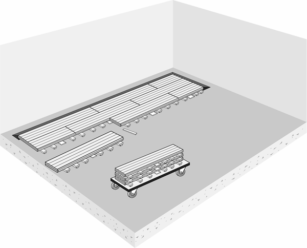
Storage carts: Junckers custom designed storage carts make transportation and storage of the panels easy.
Read all information: Please note that full documentation of a this floor system comprises General information and Specifier's and Installation instructions, see table 1.
2. GENERAL REQUIREMENTS
Climatic Conditions:
The relative humidity in the building must be in the humidity range expected for future use, see data sheet D 1.0 - CLIMATIC CONDICTIONS.
The panels are designed to allow individual expansion of each floorboard to accomodate the expected maximum relative humidity in the building when in use throughout the year.
For RH < 70%, panels with width 517.5mm are required.
For RH > 70%, panels with width 519mm are required.
The system must be stored and/or acclimated in the same climatic environment in which it will be installed, to avoid initial cupping of the panels due to sudden changes in the relative humidity.
Time frame for use:
The floor is recommended for use up to 12 weeks. If longer down time is required, please consult our Technical department.
Flatness of the subfloor:
The subfloor must be flat according to recommendation in section 8, Flatness of the subfloor. If flatness is compromised, the performance of the floor will be compromised regarding deflection, shock absorption and ball bounce.
Backstops and heavy equipment:
If portable backstops will be placed on the floor, plywood blocking must be used in the area beneath the backstop. This can be done by using 22mm plywood strips, e.g., 70mm wide, matching the thickness of the battens/foam.
When moving heavy equipment across the floor, i.e., backstops and scissor lifts, 1 layer of 18mm plywood "tracks" must always be used to protect the playing surface.
Painted areas and on-site applied lacquer:
For heavily painted areas and floors with on-site applied lacquer, a roller application method must be used. To prevent / minimize sidebonding of the panels, the floor must be disassembled within the first 72 hours after paint / lacquer has been applied. Use a utility knife to score the paint / lacquer to create a clean break between the panels the first time the floor is disassembled. Keep recommended Paint / lacquer consumption per m².
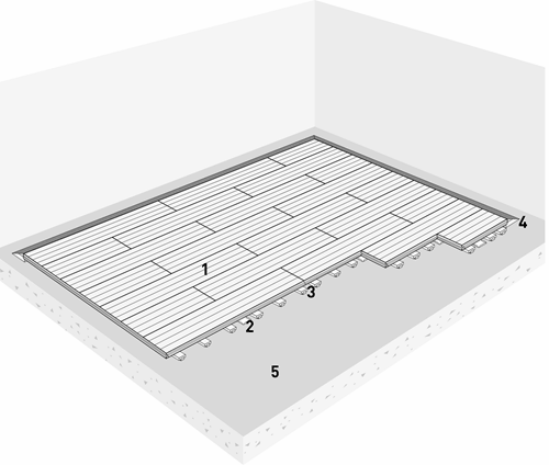
3. FLOOR COMPONENTS - PRO COMPLETE 44
1 - Junckers 22 mm solid 2-strip
floor panels.
Wood species, grade and surface:
- Beech Premium, Silk matt lacquered
- Maple Champion, Silk matt lacquered
Width x length:
Full size 0.93 m²: 517.5/519 x 1800 mm
Half size 0.47 m²: 517.5/519 x 900 mm
2 - Assembly brackets
Prefixed metal brackets.
3 - Battens
Prefixed 18 x 70 mm engineered birch battens mounted with shock absorbing foam.
Total batten height: 22 mm.
4 - Transition ramp
Black painted aluminium
5 - Moisture barrier on concrete
Min. 0.20 mm PE membrane, e.g. Junckers Moisture Barrier.
Fig. 1
4. LOAD-BEARING STRENGTH OF THE SYSTEM
Load-bearing strength of the system depends on the type of load, see table 2.
See also data sheet D 1.0 - Stiffness and load-bearing strength of floors.
|
TABLE 2 |
Loading types |
|||
|
System |
Area load |
Point load |
Point load |
Wheel load |
|
PC 44 |
1.000 kg |
350 kg |
500 kg |
See D 1.0 Table 1 |
5. CHOICE OF SUB FLOOR
The sub floor must be dry, self-supporting and made of concrete or lightweight concrete.
6. BEFORE BEGINNING TO INSTALL THE FLOOR
The building must be weather tight. The heating system must be installed and tested. During the heating season there should be a constant heat supply.
Cast concrete elements, including casting of sockets for fixtures and fittings, screeding and other wet trades which can contribute moisture to the building, e.g. priming of paintwork, must also be completed.
The relative humidity in the building must be within the relative humidity range expected, when the building is in use and the room temperature between 18 and 25°C.
7. MOISTURE PROTECTION
The residual moisture contained in the concrete or screed must not exceed 90% RH.
UK: 75% acc. To BS 8201).
On concrete sub floors with risk of moisture penetration, a moisture barrier of 0.20 mm PE membrane, e.g. Junckers Moisture Barrier, is laid directly on the sub floor.
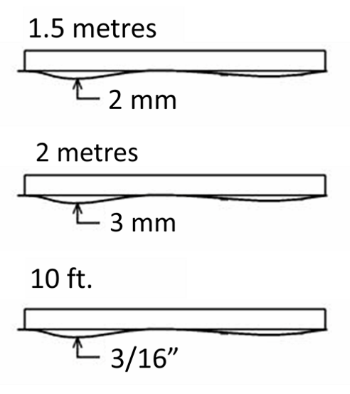
8. FLATNESS OF THE SUB FLOOR
The subfloor must be levelled so that any deviations in the flatness do not conflict with the requirements of the method stated below.
Straight edge:
The subfloor must be flat with a maximum deviation of 2 mm under a 1.5 m straight edge.
(UK: 3 mm under a 2 m straight edge).
US: 3/16” under a 10 ft. straight edge).
Deviations are measured as gaps under the straight edge. The surface must be smooth. Any irregularities must be corrected by grinding or by using a self levelling compound.
9. NET CONSUMPTION OF MATERIALS
Net consumption for a 608 m² basketball court according to the official FIBA rules 19 x 32metres (including a 2 metres safety zone around the court):
Full size panels: 665 pcs.
Half size panels: 38 pcs.
Loose tongues: 717 pcs.
Moisture barrier, 0,2 mm PE-foil: 700 m² incl. overlaps.
Extracting hook: For extracting loose tongues when dismantling the floor.
Optional:
Center Row panels.
Storage carts. One cart stores 40 full size panels.
The calculated floor area:
The calculated m² of the floor will due to the floor panel size in most cases be slightly larger than the specified floor area.
HOW TO INSTALL THE FLOOR
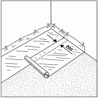
1. MOISTURE BARRIER
A moisture barrier of min. 0.20 mm PE membrane is laid, e.g. Junckers Moisture Barrier.
The moisture barrier is laid with an overlap of 200 mm at all joints. The polythene has to be taped at all lap joints using a tape 50 mm vide.
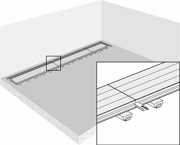
2. INSTALLATION - FIRST ROW
Keep a 500 mm distance to the wall and fixed installations in order to allow free access and mounting of loose tongues.
The first row of panels are laid in a straight line with the metal bracket pointing in the laying direction.
The panels are joined at ends by using loose joining tongues (See the small drawing).
All the panels should be numbered on the back side or on the metal bracket, to ensure that they are correctly placed each time the floor is laid, so that line markings, etc. are aligned.
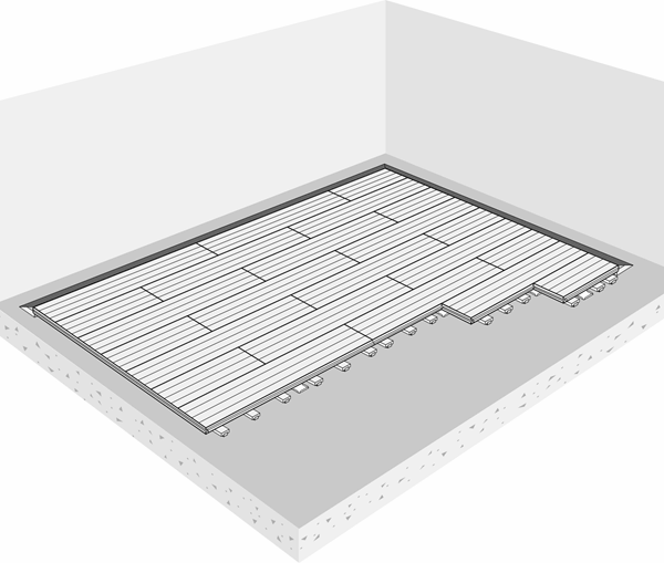
3. INSTALLATION - THE FOLLOWING ROWS
The panels are laid in an interlocking pattern so that all end joints are staggered 900 mm from row to row.
The panels are pressed close together in lengthwise tongue and groove joints before they are pressed down into the metal bracket, eg. by using a rubber hammer.
Panels without the metal bracket are used for the last row.
4. SUPPORTING TRANSITION RAMP
A supporting and protecting transition ramp forms a strong edge of the floor perimeter.
Start with the 8 corner profiles and then adjust the ramp. Use a rubber hammer if necessary.
Make sure the ramp is in correct position in order to support the panels (see small picture).

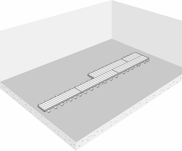
5. FLEXIBLE INSTALLATION - CENTER ROW PANELS
Centre Row panels are available on request with this floor type.
These panels come with metal brackets on each side and are laid out in the middle/centre of the floor as a starting row.
In this way two installation teams can work at the same time.
6. DISMANTLING
Remove loose joining tongues using the removal hook, and dismantle the panels row by row starting with the last installed panel.
Carefully take up the panels and stack them in the storage carts. Panels are stacked face to face and back to back, and staggered 5 cm so that the battens support each other leaving no pressure on the foam.
The panels must be stored in the same relative humidity as when the floor is in use.